
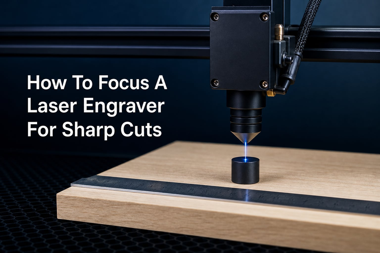
Sharp laser cuts start with focus, not with more power. When the beam reaches its smallest spot at the material, its energy is concentrated instead of spread across a wide, weak area.
This guide explains how to focus a laser engraver for sharp cuts, whether you have a diode laser, a CO2 laser, a fixed-focus head, or an adjustable lens. You will set the correct focal distance, check the result with a simple test, and know when thick stock needs a different approach.
Focus settings are not universal. The correct height comes from your machine and lens, while the best setting can change with material thickness, the job type, and whether you are engraving or cutting.
Safety comes first: Use the laser only with the safety equipment and enclosure specified by its manufacturer. Keep hands away from moving parts, never bypass interlocks, supervise every job, and use suitable ventilation because many materials produce hazardous fumes.
Laser focus is the narrowest and most intense part of the beam
Laser focus is the point where the laser beam becomes narrowest and has the greatest power density. That point is called the focal point, and it is where a cutter can make the finest line and transfer energy most effectively.
A lens brings the beam inward and then lets it expand again, creating an hourglass-like shape. The narrow middle is the beam waist; placing the work surface at that waist makes engraving crisper and improves the chance of cutting through material.
The focal length is the optical distance from the lens to its focal point. In everyday machine setup, the number you adjust is usually called focal distance: the physical clearance from a stated reference point on the laser head or nozzle to the material surface.
A focal range gives you useful tolerance around the focal point
The beam is not only usable at one mathematically perfect height. Its focal range, sometimes called focal depth, is the small zone around the beam waist where the spot remains sufficiently tight for useful work.
A smaller spot can make very fine detail, but it may have a shallower useful range. A longer focal length often has a wider range and can be more forgiving in thicker material, though the exact behavior depends on the optical system.
That is why a setting that produces a dark, narrow engraving mark at the surface may not produce the best deep cut. For a cut, you care about how the beam behaves through the material thickness, not only at the top face.
An unfocused beam wastes power and widens the cut
When the material is above or below the focal point, the beam spot grows. The same laser output is then distributed over more area, reducing power density and making the kerf wider, softer, or incomplete.
Common signs include fuzzy engraving edges, a broad charred line, shallow marks at settings that used to work, and a cut that almost reaches the back of the sheet but does not break through. More power or slower speed can sometimes hide the problem, but they do not correct the beam geometry.
Start with focus whenever a familiar material suddenly gives disappointing results. It is a quick check, and it prevents needless changes to speed, power, or pass count.
How to focus a laser engraver for sharp cuts follows a simple height-setting routine
For most machines, focus is a short process: make the machine safe, identify the manufacturer’s reference distance, bring the head or bed to that distance, secure the setting, and run a small test. Do not rely on a distance copied from a different machine because nozzle positions and lenses vary.
Step 1: Make the laser safe before adjusting its height
Turn the laser off or use the machine’s approved setup mode before putting a spacer, gauge, or material under the head. Place the actual material on a flat, supported part of the bed, since focusing on a scrap of different thickness defeats the measurement.
Check that the work is flat. A warped board can be in focus at one corner and out of focus at another, which looks like a power problem even when the power setting is unchanged.
For a moving gantry machine, move the head to a clear, accessible area before making adjustments. Keep the laser head away from clamps and hold-down hardware.
Step 2: Find the distance reference your machine specifies
Look in the machine documentation for the stated focusing method. It may specify a focus spacer between the nozzle and material, a fixed laser-head height, a lens-to-surface distance, a Z-axis value, or an autofocus command.
Use the same reference point the documentation uses. Measuring from the wrong part of the head, such as the lens housing instead of the nozzle, can produce a consistent but wrong focal distance.
If the documentation distinguishes engraving focus from cutting focus, write both settings down. Community discussions often report that users need to refocus between those operations because their preferred focal points are not always identical.
Step 3: Set the Z-axis or laser head to the stated height
On a machine with an adjustable bed, raise or lower the Z-axis until the material reaches the correct distance below the head. On a fixed-bed diode laser, loosen the height adjustment, position the laser module, then tighten it without shifting the head.
Make slow, small changes near the final position. If your adjustment has a lock screw or clamp, support the module while tightening so it does not drop a few millimeters after you set focus.
Autofocus machines still deserve a quick check. Confirm that the sensor is clean, the material is where the machine expects it, and the automatic routine is designed for the material and head currently installed.
Step 4: Remove every setup tool before the job begins
Take out the focus spacer, ruler, gauge block, and loose scraps before framing or running the design. A forgotten spacer can collide with the head, move during the job, or create a fire risk.
Then frame the design at low-risk settings if your machine supports that function. Framing verifies placement, while a focus test verifies beam sharpness; both checks matter, but they answer different questions.
Step 5: Run a small test on matching scrap
Use a scrap piece of the same material, thickness, and surface finish as the final work. Material coatings, moisture, glue layers, grain, and color can all change how a mark or cut looks.
Run a short line, a small filled square, or a compact cut shape using settings that are already reasonable for that material. The best focus normally produces the narrowest clean line, the most defined engraving detail, or the strongest cut for the selected speed and power.
Record the material, thickness, focal setting, operation, speed, power, and pass count. A small settings log is more useful than trying to remember an exact head position after a long gap between projects.
Useful habit: Set focus after placing the final material and before every job that changes thickness. A sheet that is only slightly thicker or thinner can move the surface outside a tight focal range.
A focus spacer sets the manufacturer-specified distance quickly
A focus spacer is a block, tab, or stepped gauge supplied with some engravers. It represents the required gap between the designated part of the laser head and the material, taking guesswork out of manual focus.
Place it exactly where the manual shows, lower the head or raise the bed until the spacer just fits, lock the adjustment, and remove the spacer. “Just fits” should mean light contact or the intended clearance, not compression that bends a thin gauge or pushes the work down.
A replacement spacer must match the documented dimension
Spacers are easy to misplace, and hobbyist discussions frequently mention improvised substitutes. A coin, stack of paper, or random block is only suitable if you have measured it accurately and it matches the distance specified for your exact machine.
Do not assume that a similar-looking spacer from another laser is correct. Even similar diode modules can have different nozzle-to-lens geometry, and an incorrect substitute creates an avoidable focus error.
A caliper or a clearly marked rigid gauge is preferable to compressible material. If you make a replacement, label it with the machine, lens or module, and reference point so it does not get confused with another accessory.
A manual measurement works when no spacer is available
If your machine manual gives a focal distance but no tool, measure from the specified reference point to the material with a ruler, depth gauge, or caliper used safely with the machine inactive. Keep the measuring tool square to the surface rather than angling it under the nozzle.
If you do not know the documented distance, do not invent one. Use a controlled focus test to find the setting that gives the smallest, cleanest result, then make a dedicated spacer from that verified distance.
Mark the spacer as a setup aid, not as a universal cutting setting. Focus can still need adjustment for a different lens, a different module, or a material-thickness strategy.
Thick stock cuts best with focus placed near its midpoint
For thick material, focusing exactly on the top surface concentrates the beam at the entry point but allows it to spread as it travels downward. Focusing near the middle of the thickness can place more of the focal range through the cut and produce a more even kerf.
This midpoint approach is a starting method, not an excuse to exceed a laser’s safe or practical cutting capability. If the material cannot be cut cleanly within a sensible pass count, test a thinner piece or choose a process better suited to the job.
Step 1: Calculate an initial midpoint position
Begin with the normal surface-focus setting for your material. Then move the focal point downward by about half the material thickness, following the direction convention of your Z-axis or head adjustment.
For example, a 6 mm sheet starts with a focal point about 3 mm below its top surface. The machine’s documented reference distance remains the baseline; you are deliberately offsetting the work relative to it.
Run this test on scrap because material structure matters. Plywood glue lines, wood grain, acrylic type, and small changes in thickness can change the result.
Step 2: Compare surface focus and midpoint focus with the same job
Make two small test cuts with the same artwork, speed, power, air assist setting, and number of passes. Change only the focus position so the comparison gives useful evidence.
Look at the top and bottom kerf, not just whether a piece falls out. A better thick-stock focus often gives a more balanced cut wall and stronger penetration, while a poor setting may leave a narrow top cut and a much wider, weak bottom mark.
Air assist can help clear smoke and debris from a cut, but it does not replace focus. Keep its setting consistent during a focus comparison.
Step 3: Refocus between deep passes when the process calls for it
Some deep-cut workflows use multiple passes with a small Z adjustment between them. The idea is to keep the active focal region closer to the advancing cut rather than leaving it at the original surface for the entire job.
Make these changes deliberately and record them. A random head-height change between passes makes it difficult to tell whether improvement came from focus, reduced smoke, or normal material variation.
Watch for heat buildup, discoloration, flare-ups, and excessive charring. More passes are not automatically better if the material is overheating or the kerf is filling with debris.
Material warning: Do not laser-cut an unknown plastic or coated material. Identify the material first and follow your machine maker’s safety guidance, especially for ventilation and allowable materials.
A focus test verifies the actual best setting instead of relying on guesswork
A focus test turns a subjective setup into a repeatable choice. It is especially helpful after changing a lens, cleaning optics, fitting a new laser module, moving the machine, or finding that a familiar material no longer cuts the same way.
A stepped line test finds the narrowest mark
Set up a row of identical short lines or small squares on scrap material. Between each mark, move the Z-axis or head by a consistent small increment while holding speed, power, air assist, and design constant.
Label the positions before you run the test so you know which height produced each mark. Compare line width, edge definition, darkness, and cut depth after the material cools.
For engraving, the preferred result is often the finest clearly defined line at the required darkness. For cutting, prioritize the cleanest penetration and controlled kerf, because the darkest surface mark is not always the best cutting focus.
A ramp test maps focus across several heights in one pass
A ramp test uses a piece of scrap held at a shallow angle. As the laser travels along the slope, the material passes through many focal distances, leaving a line whose narrowest or deepest section shows the best height.
Keep the material firmly supported so it cannot shift, and use a shallow enough angle to make the focus zone easy to inspect. Mark the height or distance at the best section, then confirm it on flat scrap before relying on it for a project.
This test is useful when you do not have the manufacturer’s spacer or when the stated setting no longer produces clean work. It also reveals whether the machine can reach its expected focus height with the current bed and workholding arrangement.
Visual checks reveal whether the beam is close to focus
A focused engraving usually has clean boundaries and fine detail, while an out-of-focus mark can look broad, soft, and overly scorched. A focused cut tends to show a more controlled kerf and improved depth for the same settings.
Do not judge by the visible aiming dot alone unless your manufacturer specifically says it represents the cutting beam focus. Visible pointers and work lights are useful for placement, but they are not a substitute for a material test.
Some users mention beeping or crackling sounds as an additional clue during cutting. Treat sound as a secondary observation only, because material, air flow, enclosure acoustics, and power settings can change it dramatically.
A record of successful settings saves time on the next job
Write down the confirmed focal distance or spacer method beside the material profile. Include whether the setting was for surface engraving, a through-cut, or a midpoint-thickness test.
Photographing the best test sample with its label can help when two settings look close. These records are particularly helpful for wood and acrylic, where material batches can vary even when the nominal thickness is the same.
Repeat a small verification test when your results change. It is faster than starting a large design with an uncertain focal point.
Lens and machine type change the focusing method, not the goal
Every laser needs the beam concentrated at the intended working depth, but the adjustment method differs. A diode laser may use a fixed-height module and focus spacer, while a CO2 machine may set bed height below a nozzle and lens assembly.
A diode laser often uses a spacer or adjustable module height
Many diode lasers use manual focus: you move the module or bed until a focus tool sets the gap. Some have adjustable-focus optics, where the lens or lens barrel is turned while a height setting establishes the approximate range.
Follow the module maker’s process if it specifies both a height adjustment and a lens adjustment. Turning a lens without knowing its intended reference can move the focal point far enough to create poor cuts even though the nozzle gap looks familiar.
Lens names such as G2 and three-element describe optical designs, but they do not provide a universal focus distance. Treat the exact machine documentation and a controlled test as the authority for your setup.
A CO2 laser commonly focuses by moving the bed or head
On many CO2 machines, the lens position is fixed in the head and the Z-axis moves the workbed. A focus gauge placed under the nozzle sets the material surface at the required clearance.
If focus differs from one area of the bed to another, check whether the work is flat and whether the bed is level before blaming the lens. Users also report that beam and mirror alignment can affect results across the working area, so persistent location-based changes need a systematic machine check.
Alignment work involves optical and mechanical adjustments that are specific to the machine. Refer to the manufacturer’s service procedure or qualified support rather than changing mirror screws by trial and error.
An autofocus system still needs clean inputs and confirmation
Autofocus can reduce setup time, but it does not know your cutting strategy unless the machine software and material profile account for it. If you need midpoint focus for thick stock, you may need to apply an intentional offset after autofocus.
Keep the sensor area and material surface clear of loose debris. A warped sheet, a clamp in the sensing path, or a dirty sensor can produce a height that is mechanically valid but wrong for the intended work surface.
Run a small focus test after a major material change. Automation is convenient, but verification is what protects a finished piece.
Clean optics and a level bed prevent repeat focus errors
When a once-reliable focus setting stops working, diagnose the simple physical causes before changing every software parameter. A clean, correctly positioned lens cannot compensate for a dirty optic, a tilted board, or a head that slips after its clamp is tightened.
A systematic checklist finds the usual focus problem
Confirm that the material thickness matches the setup and that the sheet is flat.
Set focus from the reference point specified for your laser head or nozzle.
Check that the Z-axis, bed, or module-height clamp remains secure after adjustment.
Inspect the lens window, protective window, and mirrors where applicable for contamination, following the manufacturer’s approved cleaning method.
Run a small stepped test on matching scrap before changing power or speed.
Compare results in the center and corners of the bed to identify flatness, leveling, or alignment concerns.
Work through one item at a time. Changing focus, power, speed, air assist, and material all at once can produce a good-looking test without telling you what actually fixed the issue.
Dirty optics reduce effective power even at the correct height
Smoke residue and dust on optical surfaces can scatter or absorb energy. The symptom can resemble poor focus: weak cuts, excess charring, or less consistent engraving.
Use only the cleaning process and materials approved by the laser manufacturer. Abrasive wiping or unsuitable solvent can damage coatings, and a damaged lens is not corrected by repeatedly changing Z height.
Check optics on a sensible maintenance schedule and after smoky jobs. Air assist and good extraction reduce residue, but they do not eliminate the need for inspection.
Bed variation makes one focus setting fail across the work area
Test the same small shape near the center and near several edges of the usable bed. If a single focus setting works in one location but not another, measure the material support and inspect the bed for debris, sag, or poor leveling.
Use a flat support method that fits the material and machine. For thin stock, hold-downs must secure the sheet without lifting or bending the area being cut.
If the pattern persists after the bed and material are confirmed flat, follow the machine maker’s guidance for gantry squareness and optical alignment. These are mechanical or optical accuracy issues rather than a normal material-focus adjustment.
Separate engraving and cutting profiles prevent accidental focus shifts
Make a separate saved profile for surface engraving and for each cutting thickness. Include the required focus height or offset in the profile name or notes so you do not start a cut using the last engraving setting.
This addresses a common maker frustration: focus seems to “move” between operations when the machine is actually still set for the previous task. A clear setup checklist makes the change visible before the job begins.
For repeat work, place the same material on the same support surface and verify the first piece. Consistency in setup is what makes stored settings dependable.
FAQs
How do I focus my laser engraver?
Set the material under the head, use the focal distance or focus spacer specified for your exact machine, lock the Z-axis or module height, remove the tool, and test a small mark on matching scrap. The best setting makes the beam spot smallest and gives the cleanest mark or cut for the job.
How do I make a laser beam more focused?
Set the correct focal distance first, then verify it with a stepped line test or ramp test. If the beam remains weak or broad at the proven height, inspect the material for warp and clean the optical surfaces using the manufacturer-approved method.
Can you focus a laser for thick material?
Yes. Begin by placing the focal point near the midpoint of the material thickness, then compare that result with surface focus on scrap using identical settings. A midpoint setting often gives a more balanced kerf through thick stock.
How do I manually focus a laser cutter without a focus tool?
Use the documented distance for your model and measure from the stated reference point on the head to the material. If the distance is unknown, perform a controlled stepped-height or ramp test, verify the best result on flat scrap, and make a labeled rigid spacer from that measured setting.
Why is my laser engraver out of focus?
The material may be at the wrong height, warped, or supported unevenly; the head clamp or Z-axis may have moved; or dirty optics may be reducing performance. Check those items one at a time and run a small focus test before changing your speed or power settings.
Correct focus turns available laser power into cleaner cuts
To focus a laser engraver, set the material at the manufacturer-specified focal distance, confirm the head stays put, and test on matching scrap. For surface engraving, focus at the surface; for thick cuts, test a focal point near the material midpoint.
When results are weak or blurry, return to the basics: flat material, correct reference point, clean optics, a secure Z-axis or module, and one controlled focus test. That short routine gives you sharper detail, more predictable depth of cut, and fewer ruined workpieces.